-
Notifications
You must be signed in to change notification settings - Fork 6
4. ONE‐PIX Hardware
| Component | Model |
|---|---|
| Rasberry pi board | 4B with 8Go RAM |
| Spectrometer | |
| Optics |
|
| Video projector | Viewsonic PA503X |
| RGB camera | Module camera V3 with CSI cable >300mm |
The ONE-PIX box is made of 6 sides and work under the principle of nested boxes.
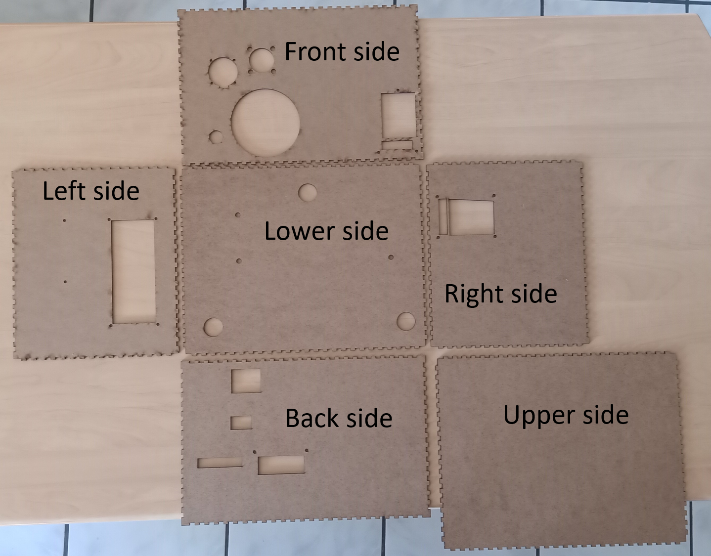
The machining of the sides is made by laser cutting of 3mm ticks MDF board. The easiest way to have access to a laser cutter is to go to the nearest fablab.
Plan of sides can be found here.
- Call and book one-hour time on the nearest fablab
- Save all cutting plan on your USB key
- Go to the Fablab with your key to cut the 6 sides of the ONE-PIX kit box
⚠️ Before using laser cutter in your fablab just talk with fabmanagers for help and learn the using modality of the laser cutter
There are seven pieces to 3d print. 3 of them are aeration parts to be fixed on the ONE-PIX kit box and others are components fixation parts. STL files for the 3D printing can be found here
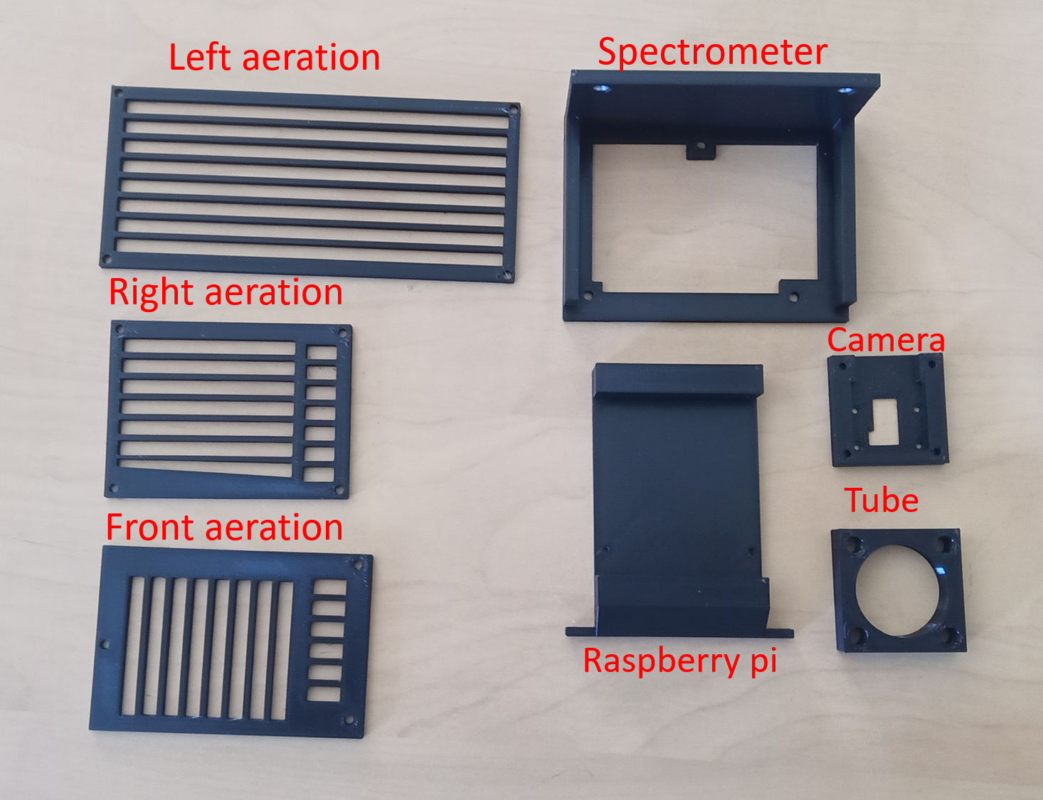
- Download STL files from this folder
- Slice each part with your favorite slicer
- 3D print every pieces
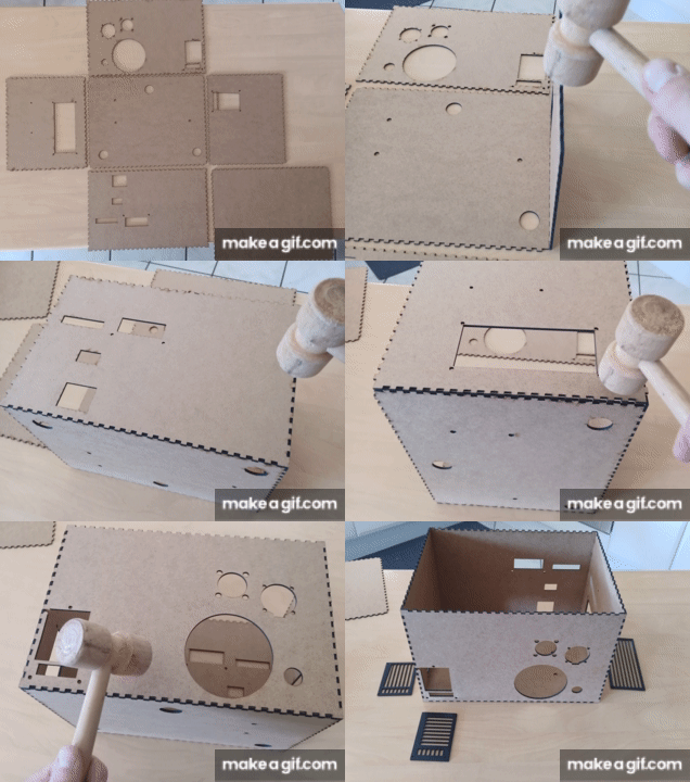
Firstly, it is necessary to assemble the sides of the box. These must be arranged as below: For assembly, simply position one face in relation to the other with a tangle of slots then tap with a mallet (without too much force) until the nesting in abutment.
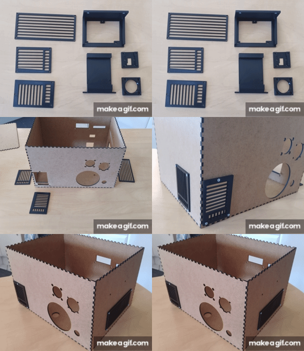
In a second step after the assembly of the MDF parts, it is necessary to fix the ventilation parts printed in 3d on the box using M3 screw and nuts
After fixing the air vents, it is necessary to mount and fix the components inside the ONE-PIX box:
- You must start by attaching the video projector to the underside with M4 screws.
- Then you have to fix the spectrometer on its support then everything on the left side of the box
- Fix the Raspberry pi on its support with M2.5 screws then fix everything on the rear side of the box with M3 screws
- Fix the RGB camera on its support with M2 screws then fix everything with M3 SCREWS on the front of the box Secure the optical tube support to the front using M6 screws and nuts
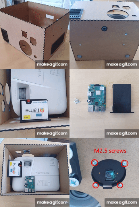
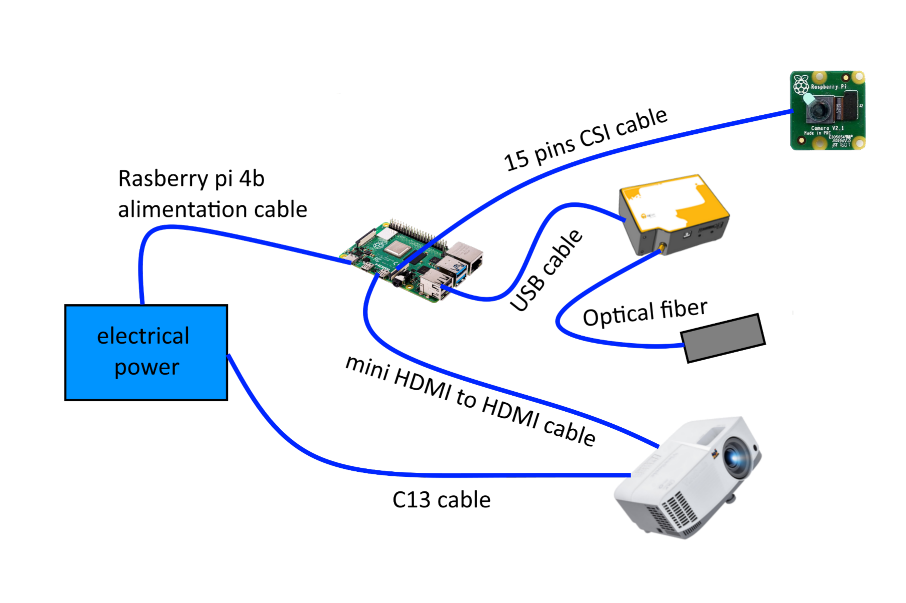
- Connect the Raspberry pi camera wire on the Raspberry Pi board
- Connect once end of the optical fiber on the spectrometer and the other to the optical tube
- Connect the HDMI end to the connector of the video projector at the back side. Pass the mini HDMI end through the cable windows at the bask side and plug it in the HDMI11 port of the Raspberry pi.
- Pass the spectrometer USB cable end through the cable window as the back side of the box and plug in the USB 2.0 port of the Raspberry pi
- Plug the USB-C Raspberry pi alimentation end by the cable windows at the back side of the box and plug in to the Raspberry pi
- Plug the C13 cable on the video projector