-
Notifications
You must be signed in to change notification settings - Fork 1
How to use the Smart Configurator
ShunichiroNakamura edited this page Sep 16, 2022
·
5 revisions
- Give an outline of how to use Smart Configurator for RX
- Describe based on the operation of e2 studio 2020-07 and CS+ V8.03(Recheck in CS+ 64-bit version)
- Call Smart Configurator "SC" in this page
- SC is a utility with the concept of "Enables to combine Software freely"
- SC mainly provides the following functions.
-
Introduce and set driver software and middleware utilizing RX MCU peripheral functions
(These soft/middleware are provided as the following components)- Firmware Integration Technology (FIT) module
- Code generation(CG)module
-
Clock and pin setting with GUI
-
Function to generate source
-
- Refer to the following applications for details
In Timer system represented by CMT and communication system represented by SCI, its setting values need to be adjusted by software according to the clock speed of clock signal wired to each.
- Users originally need to perform the coding of this software by referring to the MCU manual. However, as it has a wide variety of setting items, we have prepared a mechanism to support this by tools like SC.
- Users (especially application designer) can instruct from software to hardware without worrying about what MHz the clock source is or how the setting inside PLL is, for example “baud rate is 115200bps” with API level, thereby improving software development efficiency.
- In addition, designers with full knowledge of RX family products perform development and maintenance (continuous bug fix) of the driver software for RX family-mounted circuit, such as CMT, SCI, Ether, USB and SDHI with API design in “FIT module” format for major RX group and distribute FIT module packaged by one as “RX Driver Package”
- Therefore, users can focus on the application development without worrying about detailed hardware differences in RX family products and hardware errata information.
- Create project from scratch
-
File->New->Project -
Wizard->C/C++->C/C++ Project->Next-
All->Renesas CC-RX C/C++ Executable Project- Enter any name on
Project name->Next*Select device inDevice Settings->Target device- Select RTOS and version in
Toolchain Settings->RTOS -
Configuration-> GenerateHardware Debug configuration->Select emulator you use - Select other setting as you like ->
Next-
Use Smart ConfiguratorにCheck ->Exit
-
- Select RTOS and version in
- Enter any name on
-
-
- Double click
[Project name].scfgof newly created project- SC is booted
- Create new project
-
File->Create new project -
Wizard->Microcontroller->RX-
Microcontroller which is used-> Select device which is used -
Project type->Application (CC-RX) - Enter any name in
Project name->Next - Select other setting as you like ->
Create
-
-
- Double click
Smart Configurator (Design tool)of newly created project- SC is booted
- Press
Boardtab on the bottom of the SC screen - Select board you want to use from
Boardcategory (Read Board Configuration File(BDF) into project)- By reading BDF, "pin setting" on Smart Configurator is automated.
- ★Future improvement★ The settings of component and clock will be fully automated.
- If your intended board does not appear as option, BDF can be installed from
Download board information.- ★Future improvement★ BDF will be able to be selected and installed with project creation wizard.

- By reading BDF, "pin setting" on Smart Configurator is automated.
- ★Future improvement★ In tandem with BDF The setting will be unnecessary in e2 studio 2020-xx (Future version) (necessary before e2 studio 2020-07)
- Press
Clocktab on the bottom of SC - By changing the values of check box and pulldown menu, perform clock setting
- Check build error(Not required but recommended)
- Execute Generate code temporarily, and skeleton program according to the content which is set with SC is outputted.
- Execute the build of project, and check that an error is not displayed on the console.
In the case of * e2 studio ,execute
Project->Build allon the top screen of e2 studio to build.
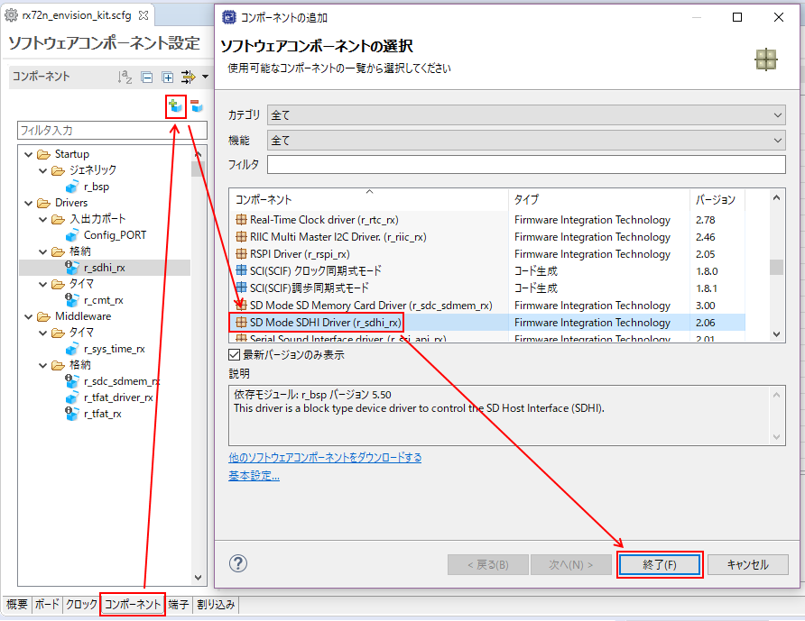
- Press
Componenttab on the bottom of SC screen - Press
Add componentinComponentpane on the left of SC screen - Select component (FIT or CG)you want to add in the added window
(Can select several components by clicking while pressing Ctrl key) - Check that the component which you added in the above step is displayed on
Componentpane on the left of SC screen.
- Select
basic settinginSelect software componentwindow, and checkDisplay all FIT modules - If your intended FIT module is not displayed by following the above step, check if the module exists in Save destination folder of FIT moduleor not.
- Access Save destination folder of FIT module
- Check that the intended FIT module exists in this file path
- If it exists, reboot IDE, while SC is closed, and check again if your intended module exists or not.
- If it does not exist, import FIT module manually
Official document:Firmware Integration Technology (FIT) -> RX Family Manually Importing Firmware Integration Technology Modules
- Obtain your intended FIT module from RX Driver Package (RDP)
- Copy the FIT module obtained in the above step to Save destination folder of FIT module.
- After closing SC, boot IDE and check again if your intended module is displayed or not.
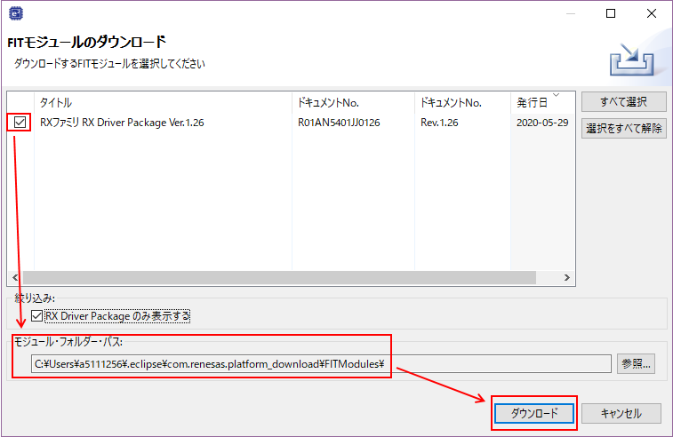
- FIT module displayed in component adding operation refers to the following folder (Save destination folder of FIT module)
- The file path which is set in
Add component->Basic setting->Module Download->Location (RX)- Default of e2 studio:
C:\Users\[User name]\.eclipse\org.eclipse.platform_download\FITModules
- Default of e2 studio:
- One FIT module consists of the following files(x: Function name, n: version)
-
r_xxx_vn.nn.zip:Module itself in which source code and documents are compressed. -
r_xxx_vn.nn.xml:Module information file necessary to SC liaison -
r_xxx_vn.nn.mdf:Definition file which is used for SC component setting(Only some FIT modules) -
r_xxx_vn.nn_extend.mdf:Definition file which is used for SC component setting(Only some FIT modules)
-
- The file path which is set in
- Right after manually adding FIT module, it is not recognized by Smart Configurator.
- Reboot e2 studio or CS+ temporarily
- RX Driver Package (RDP) is a free package including BSP for RX MCUs, driver and middleware.
- The above software is provided as FIT module.
- The version of included FIT module varies with that of RDP.
- By clicking
previous version informationof bottom of the page, you can refer to a link destination of the previous versions of RDP. - To have Smart Configurator recognize the FIT module included in the previous RDP versions, you need to operate manually ⇒ [Save destination folder of #FIT module ](Save destination folder of #FIT module)
- By clicking
- You can download RDP from SC(Note: only the latest version)
-
For the MCUs before RX64M model such as RX63N, use FIT module with RDP V1.19
- These MCUs do not support the latest FIT module.
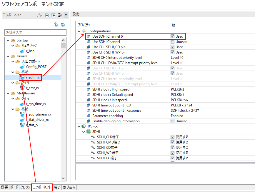
- Press
Componenttab on the bottom of SC screen - Select a component you want to set in
Componentpane on the left of SC screen. - Change the setting in
settingpane on the center of SC screen.
- Execute according to the situation
- Press
Componenttab on the bottom of SC screen - Right-click a component of which you want to change the version in
componentpane on the left of SC screen. - Press
Change versionin the context menu which is displayed - In the displayed window、Specify the version of the change destination
Version after the change->Next - Check setting items which are changed in the screen of changed setting which will be displayed next. -> If there is no problem,
Exit - Generate code is automatically executed, and component version is changed.
- Right-click the component of which version was changed in
Componentpane on the left of SC screen. -> PressChange versionand check that the version has been automatically changed.
- Execute according to the situation
- Press
Componenttab on the bottom of SC screen - Select a component you want to delete in
Componentpane on the left of SC screen - Press
Delete componentinComponentpane on the left of SC screen - Press
Yesin the displayed window for checking. - Check that your intended component is deleted in
Componentpane on the left of SC screen.
- Press
Pintab on the bottom of SC screen - Select the resource of a pin you want to set in
Hardware resourcepane on the left of SC screen. - Check the box of
UseinPin functionpane on the center of SC screen to select pins which you want to use. - Change pulldown menu of
Pin assignmentinPin functionpane on the center of SC screen to set the port number of a pin you want to use.
- [Note] not linked with FIT interrupt setting
- Press
Interrupttab on the bottom of SC screen - Select an interrupt you want to use to set the function of
Interruptandpriority level. - Select an interrupt you want to use and press
Move upwardandMove downwardto change vector number
- Press
Generate codebutton on the upper right of SC screen. - Program code according to the content which is set on SC is automatically generated.
- Execute build of the project and check that an error is not displayed on the console.
In the case of * e2 studio, execute
Project->Build allon the top of e2 studio screen to build.
- The source code subject of SC control (Source program under .\src\smc_gen\) right before source generation is backed up in .\trash\folder right after executing source generation.
- OTA via AWS with FreeRTOS
- Network Benchmark
- How to use Tracealyzer
- D2 audio
- MEMS mic
- ESP32
- SSL acceleration by Trusted Secure IP(TSIP)
- Generate new project (bare metal)
- 1+SCI_
- 1+Trusted Secure IP Driver
- 1+QSPI+Serial flash driver (for Macronix)
- 1+Ether+TCP/IP_
- 1+Ether+TCP/IP+Web Server_
- 1+SDHI+SD Card Driver+Filesystem_
- 1+GLCDC+DRW2D+emWin(Segger GUI Middleware)
- 1+SSI+Audio playback and recording
- Generate new project (FreeRTOS(Kernel Only))
- Application of queue Serialization of print debug
- How to implement Tracealyzer Recorder
- How to implement Tracealyzer Recorder for complex system
- AWSとFreeRTOSを用いたOTAによるファームアップデート方法
- ネットワークベンチマーク
- Tracealyzer使用方法
- D2オーディオ活用
- MEMSマイク活用
- ESP32活用
- Trusted Secure IP(TSIP)によるSSLの加速
- 新規プロジェクト作成方法(ベアメタル)
- 1+SCI
- 1+Trusted Secure IPドライバ
- 1+QSPI+シリアルフラッシュドライバ(Macronix用)
- 1+Ether+TCP/IP
- 1+Ether+TCP/IP+Webサーバ
- 1+SDHI+SDカードドライバ+ファイルシステム
- 1+GLCDC+DRW2D+emWin(Segger GUIミドルウェア)
- 1+SSI+音声再生録音


