-
Notifications
You must be signed in to change notification settings - Fork 1
1 GLCDC DRW2D emWin(Segger GUI Middleware)
MasahikoNagata edited this page Nov 30, 2020
·
7 revisions
- Introduce a way to create interactive GUI application via liquid crystal display
- By using QE for Display[RX], perform the embedding/setting of the following driver and software.
For embedding/setting method, refer to Application note(R20AN0582xxxxxx) of QE for Display[RX], too.
- By using RX72N MCU peripheral function, graphic LCD controller (GLCDC), 2D drawing engine (DRW2D), and emWin soft by SEGGER, display letters and figures on liquid crystal display.
- By using GUI design tool AppWizard, set interactive GUI on crystal liquid display.
- Control LED lighting by touch operation of a button displayed on liquid crystal display.
- By using QE for Display[RX], perform the embedding/setting of the following driver and software.
- Indispensable
- RX72N Envision Kit × 1 unit
- USB cable (USB Micro-B --- USB Type A) × 1
- Windows PC × 1 unit
- Tools to be installed in Windows PC
- e2 studio 2020-07 or later
- Initial booting sometimes takes time.
- CC-RX V3.02 or later
- Initial booting sometimes takes time.
- e2 studio 2020-07 or later
- Tools to be installed in Windows PC
-
Generate new project (bare metal) must be completed.
- In this section, implements by adding the following for LED 0.1 second cycle blinking program generated by Generate new project (bare metal).
- Utilizing QE for Display, easily embed/set GLCD driver, DRW2D driver and emWin
- Using AppWizard, set GUI
- Add code to control GUI
- In this section, implements by adding the following for LED 0.1 second cycle blinking program generated by Generate new project (bare metal).
- The latest RX Driver Package(FIT module) must be used.
- Perform only the first time.
- Follow How to install to download/install QE for Display
- Download DRW2D FIT module, and emWin FIT module and locate them in Storage destination folder of FIT module.
This is because DRW2D FIT module and emWin FIT module are not supplied by RX Driver Package V1.26
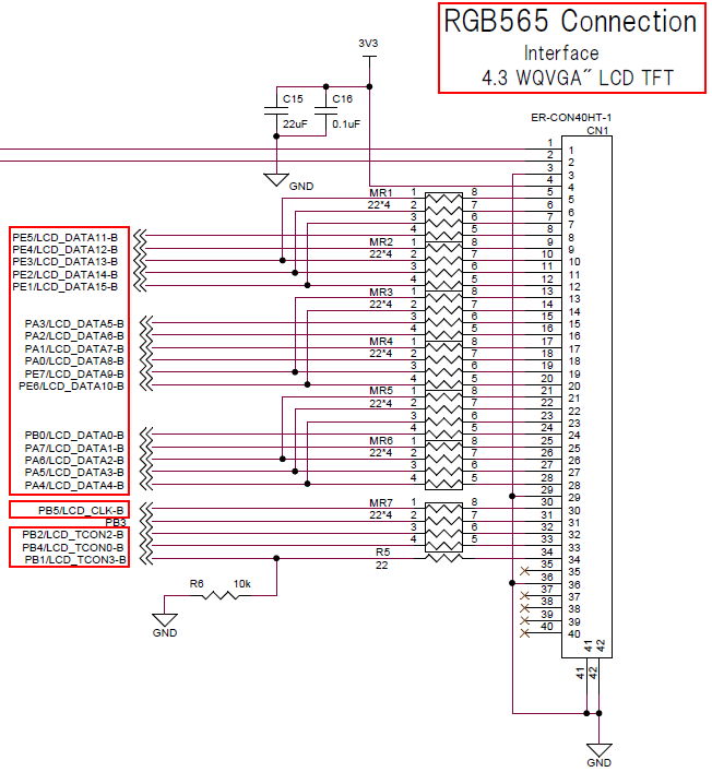
- Check the LCD related circuits as described below.
- 4.3 inch WQVGA TFT-LCD is installed in RX72N Envision Kit.
- Output data format is RGB565 format (Paralle,16bit)
- RGB565 is a format to express colors with the total 16bit(65,536 colors) of 5bit of R/B and 6bit of G.
- By the way, the reason why G is 1bit larger than R or B is that green is the color which reacts to the human eyes most easily.
- RGB565 is a format to express colors with the total 16bit(65,536 colors) of 5bit of R/B and 6bit of G.
- In the case of RGB565, the pin which outputs data to LCD (LCD signal output pin) is 16bit bus of LCD_DATA15 to LCD_DATA0.
Refer to (3) of 51.1.5 of RX72N Hardware manual(R01UH0824xxxxxx)
- However, the pixel array of GLCDC has two types, R-G-B and B-G-R. By using the function to switch B/R, pixel array ordering can be switched.
- Data pins of LCD (LCD_DATA_11~LCD_DATA_15) function as color data output pin of R in the case of R-G-B pixel array, and as color data output pin of B in the case of B-G-R pixel array.
- Data pins of LCD (LCD_DATA_0~LCD_DATA_4)function as color data output pin of B in the case of R-G-B pixel array, and as color data output pin of R in the case of B-G-R pixel array.
- Refer to “The bit position of LCD signal in parallel RGB(565) format” in RX72N hardware manual 47.1.5 (3) for details.
- However, the pixel array of GLCDC has two types, R-G-B and B-G-R. By using the function to switch B/R, pixel array ordering can be switched.
- Also, panel clock output pin (LCD_CLK) and synchronous signal output pin (LCD_TCON3~LCD_TCON0) are used.
Refer to table 51.2 of 51.1 of RX72N Hardware manual(R01UH0824xxxxxx).

- Output data format is RGB565 format (Paralle,16bit)
- The capacitance touch controller (FT5260) is installed in RX72N Envision Kit
- RX72N MCU performs data communication with the capacitance touch controller at I2C serial interface,
and controls controller operation.
- Check that BDF
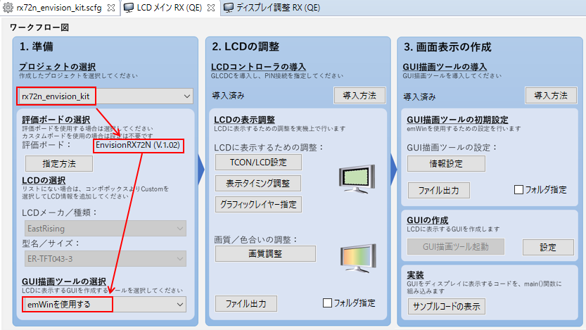
EnvisionRX72Nis applied to the project- Refer to How to use Smart Configurator#Board setting
- If it is not applied, see the above link for how to handle this.
- Execute
Renesas Views->Renesas QE->LCD main RX (QE)and open QE for Display - Select
rx72n_envision_kit, the project which applies QE for Display from the pulldown menu ofSelect projectof QE for Display. - After selecting it, check that
evaluation boardbecomesEnvisionRX72N (V.x.xx).- Since BDF
EnvisionRX72Nis applied to the project,evaluation boardautomatically changes when selecting a project withSelect project
- Since BDF
- Select
Use emWinwithSelect GUI drawing tool 
- Describe how to set LCD controller below.
- Install LCD controller (GLCDC FIT module)into the project with Smart Configurator (SC)
- Open SC and Add component,
r_glcdc_rx- If an error occurs due to FIT module dependency, the version of FIT modules might not be appropriate.
- According to the error content, Change version of FIT modules.
- If an error occurs due to FIT module dependency, the version of FIT modules might not be appropriate.
- Execute Generate code of SC temporarily.
- Open SC and Add component,
- Check that
LCD main RX (QE)->LCInstall D controller->Has been installed. - Perform the LCD controller setting
LCD main RX (QE)->Adjust LCD display->Adjust display timing- Since an error occurs with default "timing setting", clear the error.
-
Perform the setting in which refresh rate [Hz] and horizontal frequency [kHz]
meet each value which can be set, anddifference` becomes 0.0. (Example is shown below)-
PLL circuit frequency[MHz]:240- Change PLL circuit frequency to the same value as Clock setting of SC.
- ★Future improvement★ Plan to improve to be able to automatically obtain values from the clock setting of SC.
- Change PLL circuit frequency to the same value as Clock setting of SC.
-
Panel clock frequency [MHz]:10.000000- Set panel clock frequency to the value less than PCLKA
-
HPW:30 -
HBP:54 -
HFP:20 
-
- When using QE for Display, Set component of SC regarding r_glcdc_rx is not required
- Since an error occurs with default "timing setting", clear the error.
- Generate the setting fie of LCD controller from QE for Display.
- Execute
LCD main RX (QE)->Adjust LCD display->Output file- Output destination of default is directly under
.\rx72n_envision_kit\src. - By checking
Specify folderand executingOutput file, you can select output destination. - However, avoid locating it under
.\rx72n_envision_kit\src\smc_gen.- This is because the outputted file could be deleted by Generate code of SC.
- Output destination of default is directly under

- Execute
- Install LCD controller (GLCDC FIT module)into the project with Smart Configurator (SC)
- Refer to
LCD main RX (QE)->Install LCD controller->How to installfor details of installing method.
- Describe how to set GUI drawing tool below.
- Introduce GUI drawing tool (emWin FIT module) into the project using SC.
- Open SC and Add component,
r_emwin_rx.- FIT module which has dependency with emWin FIT is automatically added to the project by SC function.
- r_cmt_rx
- r_dmaca_rx
- r_drw2d_rx
- r_glcdc_rx
- r_gpio_rx
- r_sci_iic_rx
- If an error occurs due to FIT module dependency, the version of FIT modules might not be appropriate.
- According to the error content, Change version of FIT modules.
- FIT module which has dependency with emWin FIT is automatically added to the project by SC function.
- Execute Generate code of SC
- Open SC and Add component,
- Check
LCD main RX (QE)->Install GUI drawing tool->Have been installed - Perform the setting of emWin
-
Frame buffer 2 address:0x00840000- In this chapter, since the section setting is not changed from Generate new project (bare metal), the above value can be used.
- However, when this buffer address overlaps the section address, change the section address.
-
Maximum memory size which is used in GUI:81920 -
Channel which is used in IIC:6 -
Use DRW2D:Use 
- When using QE for Display, Set component of SC regarding r_emwin_rx is not required
-
- Generate the emWin setting file from QE for Display
- Execute
LCD main RX (QE)->Initial setting of GUI drawing tool->Output file- The output destination of default is directly under
.\rx72n_envision_kit\src. - By checking
Specify fileand executingOutput file, the output destination can be selected. - However, avoid putting under
.\rx72n_envision_kit\src\smc_gen.- This is because the outputted file can be deleted by Generate code of SC.
- The output destination of default is directly under

- Execute
- Introduce GUI drawing tool (emWin FIT module) into the project using SC.
- Refer to
LCD main RX (QE)->Install GUI drawing tool->how to installfor details of installing method.
- Since the necessary components have already been added with QE for Display, no operation is required here.
- Perform setting for the components which are not covered by the setting of QE for Display.
-
Heap size:0x4000
- No problem with default
- No problem with default
- None
- Since the setting is performed with QE for Display, no operation is required here.
- No problem with default
- Since the setting is performed with QE for Display, no operation is required here.
- Since RX72N MCU assigns multiple functions to one pin, you need to perform the setting of which function to be used.
- If BDF of RX72N Envision Kit is used, the pin setting has already been performed. No operation is required.

- After all the settings mentioned above are completed, execute Generate code of SC.
- Perform only for the first time
- Press
LCD main RX (QE)->Create GUI->Setting, to displaySet AppWizardwindow - If
AppWizard is not installedis displayed,
enter file path you want to install inAppWizard install folder->
PressInstall AppWizarad 
- When the install wizard is displayed, follow the screen instructions to install AppWizard.
- Close
Set AppWizardwindow
- Press
LCD main RX (QE)->Create GUI->settingto displaySet AppWizardwindow - If
AppWizard is installedis displayed, pressOK - If
AppWizard is not installedis displayed, perform either of the processings below.- If the display changes from
Enter file path in which AppWizard is installed in AppWizard install folder->AppWizard is installed, pressOK - Execute Install AppWizard
- If the display changes from
- Press
LCD main RX (QE)->Generate GUI->Boot GUI drawing tooland boot AppWizard. - After booting AppWizard, check that
./aw/Resourceand./aw/Sourceare generated from the project tree of e2 studio.
- The basic flow of designing AppWizard screen is described below.
- Register
Resource(Text,Fonts,Images,Variables) - Locate/install GUI object
- Select an object which you want to locate from
Add objectspane. - Check that the object you selected is added to
Hierarchc treepane. - Change the hierarchy of the object with
Hierarchc treepane. - Change the location and size of the object with
Hierarchc treepane. - Change the property of the object with
Propertiespane
- Select an object which you want to locate from
- Register the event of the object and event handler (Slot) with
Interactionspane. - Execute
File->Export & Saveand output source code
- Register
- Make sure to locate an object,
Screenon the top ofHierarchc tree
- Follow How to register Text resource to generate
ID_TEXT_LED_SWITCH_TXTとID_TEXT_OFF_TXT-
Id:"ID_TEXT_LED_SWITCH_TXT"、English:"LED Switch" -
Id:"ID_TEXT_OFF_TXT"、English:"OFF"
-
- Firstly, locate an object,
Screen
- For the background, locate an object with the size of filling the
Boxscreen.- Select
Add objects->Box - Check that an object,
Boxis added underID_SCREEN_00withHierarchc tree. - Check that an object,
Boxis added toEditor- Do not change the size (Full size must be used)
- Change
Properties-
Id:"ID_BOX_00" - Press the rectangular area in
Set colorto display color selection screen ->
Select the color for background(RGBA = (75, 75, 75, 255))->OK
-

- Select
- Locate an object,
Switchfor the LED switch.- Select
Add objects->Switch - Check that an object,
Switchis added underID_BOX_00withHierarchc tree - Check that an object,
Switchis added toEditor - Change the size of
Switch, an object onEditor.-
Properties->Size:150,50
-
- Drag and drop
Switch, an object on "Editor" and move to the center of the screen-
Properties->Position:165,111
-
- Change
Properties-
Id:"ID_SWITCH_00" -
Set Bitmaps->BG-Left:Left_80x30.png->Select -
Set Bitmaps->BG-Right:Right_80x30.png->Select -
Set Bitmaps->BG-Disabled:Disabled_80x30.png->Select -
Set Bitmaps->Thumb-Left:ThumbLeft_80x30.png->Select -
Set Bitmaps->Thumb-Right:ThumbRight_80x30.png->Select -
Set Bitmaps->Thumb-Disabled:Disabled_80x30.png->Select
-

- Select
- Locate
Text, an object for letters indicating the use of the switch.- Select
Add objects->Text - Check that an object,
Texthas been added underID_SWITCH_00withHierarchc tree - Check that an object,
Textis added toEditor - Change the size of
Text, an object onEditor.-
Properties->Size:150,32
-
- Drag and drop
Text, an object onEditor,
and move it right above an object,ID_SWITCH_00.-
Properties->Position:165,79
-
- Change
Properties-
Id:"ID_TEXT_LED_SWITCH" -
Set text color:RGBA = (255, 255, 255, 255) ->OK -
Set text alignment:Center -
Set font:NettoOT_24_Normal_EXT_AA4->Select
-

- Select
- Locate
Text, an object for letters to indicate the LED state according to the Switch state- Select
Add objects->Text - Check that an object,
Textis added underID_TEXT_LED_SWITCHwithHierarchc tree - Check that an object,
Textis added toEditor - Change the size of
Text, an object onEditor-
Properties->Size:150,32
-
- Drag and drop
Text, an object on theEditor,
and move it right beneath an object,ID_SWITCH_00-
Properties->Position:165,79
-
- Change
Properties-
Id:"ID_TEXT_LED_STATE" -
Set text alignment:Center -
Set font:NettoOT_24_Normal_EXT_AA4->Select
-

- Select
- Locate
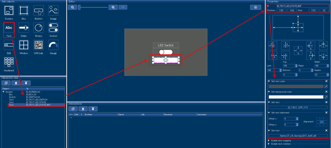
Text, an object for letters indicating the initial state of the LED- Right-click
ID_TEXT_LED_STATEofHierarchc treeand selectCopy - Right-click with
Hierarchc treeand selectPaste - Check that an object,
ID_TEXT_LED_COPYis added underID_TEXT_LED_STATEwithHierarchc tree. - Change
Properties-
Id:"ID_TEXT_LED_STATE_INIT" -
Set text:ID_TEXT_OFF_TXT->Select -
Set text color:RGBA = (80, 80, 80, 255) ->OK -
Set background color:RGBA = (255, 255, 255, 255) ->OK - Other properties are the same as
ID_TEXT_LED_STATE.
-

- Right-click
- Register event to display letters of LED state according to the switch state.
- Press
Interactions->+-
Emitter(Origin of the event):ID_SWITCH_00 -
Signal(Event type):VALUE_CHANGED(Event of value change) -
Job(Task linked to the event occurrence ):SETVIS(Setting of object display/hide ) -
Receiver(Address of linked task):ID_TEXT_LED_STATE
-
- Press
pop-up set interaction parameterswindow ->Use custom defined value-
Set visibility:On -
Slot:ID_SCREEN_00__ID_SWITCH_00__WM_NOTIFICATION_VALUE_CHANGED__ID_TEXT_LED_STATE__APPW_JOB_SETVIS - Since
Edit code:AppWizard setting and outputted source cord can be linked, After Source code output of AppWizard Edit
-

- Press
- Register event to hide letters of initial value switch state.
- Press
Interactions->+-
Emitter(Origin of the event):ID_SWITCH_00 -
Signal(Event type):VALUE_CHANGED(Event of value change) -
Job(Task linked to event occurrence):SETVIS(Set display/hide of object) -
Receiver(Address of linked task):ID_TEXT_LED_STATE_INIT
-
- Press pop-up
Set interaction parameterswindow ->Use custom defined value-
Set visibility:Off -
Slot:ID_SCREEN_00__ID_SWITCH_00__WM_NOTIFICATION_VALUE_CHANGED__ID_TEXT_LED_STATE_INIT__APPW_JOB_SETVIS -
Edit code:do not edit
-

- Press
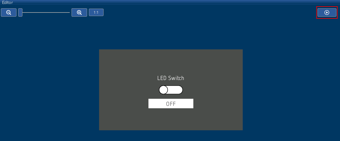
- When pressing the playback mark of
Editorpane, preview of the located object is created.- This section is designed to preview the following state.
- In initial state, the toggle of the switch is on the left at the center of the screen.
- In initial state, white "LED Switch" display is right above the switch.
- In initial state, white "LED Switch" letter display is above the switch.
- In initial state, white square is right beneath the switch, and gray "OFF" letter display is inside it.
- When click the switch, toggle switch moves to the right,
and the square and letter display right beneath the switch disappears.- After moving toggle, the square and letter display (
ID_TEXT_LED_STATE_INIT) right beneath the switch disappears, which is the intended operation. - After moving toggle,
ID_TEXT_LED_STATEshould be displayed right beneath the switch, but letter display is changed by user source code, apparently no change.
- After moving toggle, the square and letter display (
- When clicking the switch again, toggle switch moves to the left.
- This section is designed to preview the following state.

- Execute
File->Export & Save - Check that source code is outputted under
./aw/Source(Special note is described below)- Related to
Resource(Text, Fonts, Images, Variables) of Resource.h:AppWizard - ID_SCREEN_00.h:object
ID_SCREEN_00and related to an object located inside it. - ID_SCREEN_00_Slots.c:object
ID_SCREEN_00and related to Slot of an object located inside it. - Related to initialization/execution of GUI object generated with APPW_MainTask.c:AppWizard
- Related to
- Describe all the source codes of
rx72n_envision_kit.cbelow(Explained later)
#include "GUI.h"

void main(void);

void main (void)
{
    /* The follow function is generated by the AppWizard. */
    MainTask();
}- Describe all the source codes of
ID_SCREEN_00_Slots.cbelow(Explained later)
#include "Application.h"
#include "../Generated/Resource.h"
#include "../Generated/ID_SCREEN_00.h"

/*********************************************************************
*
*       Public code
*
**********************************************************************
*/
/*********************************************************************
*
*       cbID_SCREEN_00
*/
void cbID_SCREEN_00(WM_MESSAGE * pMsg) {
  GUI_USE_PARA(pMsg);
}

/*********************************************************************
*
*       ID_SCREEN_00__ID_SWITCH_00__WM_NOTIFICATION_VALUE_CHANGED__ID_TEXT_LED_STATE__APPW_JOB_SETVIS
*/
void ID_SCREEN_00__ID_SWITCH_00__WM_NOTIFICATION_VALUE_CHANGED__ID_TEXT_LED_STATE__APPW_JOB_SETVIS(APPW_ACTION_ITEM * pAction, WM_HWIN hScreen, WM_MESSAGE * pMsg, int * pResult) {
    GUI_USE_PARA(pAction);
    GUI_USE_PARA(hScreen);
    GUI_USE_PARA(pMsg);
    GUI_USE_PARA(pResult);

    int result = 0;
    /* Returns the state of a SWITCH widget. */
    result = SWITCH_GetState(pMsg->hWinSrc);
    if(SWITCH_STATE_RIGHT == result)
    {
        process_switch_on(pMsg->hWin);
    }
    else if(SWITCH_STATE_LEFT == result)
    {
        process_switch_off(pMsg->hWin);
    }
    else
    {
        process_switch_error(pMsg->hWin);
    }
}

/*********************************************************************
*
*       ID_SCREEN_00__ID_SWITCH_00__WM_NOTIFICATION_VALUE_CHANGED__ID_TEXT_LED_STATE_INIT__APPW_JOB_SETVIS
*/
void ID_SCREEN_00__ID_SWITCH_00__WM_NOTIFICATION_VALUE_CHANGED__ID_TEXT_LED_STATE_INIT__APPW_JOB_SETVIS(APPW_ACTION_ITEM * pAction, WM_HWIN hScreen, WM_MESSAGE * pMsg, int * pResult) {
  GUI_USE_PARA(pAction);
  GUI_USE_PARA(hScreen);
  GUI_USE_PARA(pMsg);
  GUI_USE_PARA(pResult);
}- Describe all the source codes of
Application.hbelow(Explained later)
#ifndef APPLICATION_H
#define APPLICATION_H
/* Custom code by Renesas */
#include "platform.h"
#include "AppWizard.h"

void process_switch_on(WM_HWIN hDisplayedText);
void process_switch_off(WM_HWIN hDisplayedText);
void process_switch_error(WM_HWIN hDisplayedText);
void led_on(void);
void led_off(void);
#endif // RESOURCE_H- Describe all the source codes of
Application.cbelow (Explained later)
#include "Application.h"

void process_switch_on(WM_HWIN hDisplayedText)
{
    TEXT_SetText(hDisplayedText, "ON");
    TEXT_SetBkColor(hDisplayedText, GUI_WHITE);
    TEXT_SetTextColor(hDisplayedText, GUI_BLUE);
    led_on();
}

void process_switch_off(WM_HWIN hDisplayedText)
{
    TEXT_SetText(hDisplayedText, "OFF");
    TEXT_SetBkColor(hDisplayedText, GUI_WHITE);
    TEXT_SetTextColor(hDisplayedText, GUI_GRAY);
    led_off();
}

void process_switch_error(WM_HWIN hDisplayedText)
{
    TEXT_SetText(hDisplayedText, "ERROR");
    TEXT_SetBkColor(hDisplayedText, GUI_WHITE);
    TEXT_SetTextColor(hDisplayedText, GUI_RED);
    led_off();
}

void led_on(void)
{
    PORT4.PODR.BIT.B0 = 0;
}

void led_off(void)
{
    PORT4.PODR.BIT.B0 = 1;
}- Execute
MainTask()function-
MainTask()function executes the initialization and main processing of emWin and AppWizard. -
MainTask()function is automatically generated by Output source code of AppWizard.
-
ID_SCREEN_00__ID_SWITCH_00__WM_NOTIFICATION_VALUE_CHANGED__ID_TEXT_LED_STATE__APPW_JOB_SETVIS() function
- Event handler when it acts on text,
ID_TEXT_LED_STATEwith toggle switch of switch,ID_SWITCH_00trigger - Distribute the processing according to toggle state when switching.
- Perform processing as switch on when toggle switches to the right.
- Perform processing as switch off when toggle switches to the left.
- Perform processing as error during toggle state other than the state mentioned above.
- Change the letter display of text,
ID_TEXT_LED_STATEto "ON" (TEXT_SetText()) - Change the background color of text,
ID_TEXT_LED_STATEto white(TEXT_SetBkColor()) - Change the letter color of text,
ID_TEXT_LED_STATEto blue (TEXT_SetTextColor()) - Turn on the LED(
led_on())
- Change the letter display of text,
ID_TEXT_LED_STATEto "OFF" (TEXT_SetText()) - Change the background color of text,
ID_TEXT_LED_STATEto white (TEXT_SetBkColor()) - Change the letter color of text,
ID_TEXT_LED_STATEto gray (TEXT_SetTextColor()) - Turn off the LED (
led_off())
- Change the letter display of text,
ID_TEXT_LED_STATEto "ERROR" (TEXT_SetText()) - Change the background color of text
ID_TEXT_LED_STATEto white color (TEXT_SetBkColor()) - Change the letter color of text
ID_TEXT_LED_STATEto red (TEXT_SetTextColor()) - Turn off the LED(
led_off())
- Turn on/off each LED
- A port to control the LED is P40(LED circuit diagram)
- Describe the key points to use AppWizard below
- AppWizard is Windows application to support users' installment of GUI object mounted on emWin.
- Users can install and set GUI object, register event, simulate operation and even generate code while watching the screen.
- The GUI object of emWin which can be used with AppWizard V1.06a_6.14a is as below (Unofficial explanation in Japanese is in the brackets below)
- Screen(Screen which is a parent of all objects)
- Box(Rectangle)
- Button(Button)
- Image(Image)
- Text(Text display)
- Slider(Slider bar)
- Rotary(Round control knob)
- Switch(Toggle switch with two values)
- Edit(Text input column)
- Window(Window screen)
- QRCode(QR code)
- Gauge(Semi-arch type progress gauge )
- Keyboard(Keyboard)
- GUI object can store location relation with each other (similar to shape group function of Excel)
- Follow the steps below
- Select one of the GUI objects which you want to relate to
- Right-click and drag one of nine □s which appear on the four sides of GUI objects to display a red line or green line.
- Drag it to near the other GUI object which you want to relate to, and stop right-clicking when turning green.
- When releasing the relating, select location option of any of

- Used for the purpose of preventing compiler warning caused by not using Slot routine function parameter.
- Although all the parameters of Slot routine functions are always used in Slot routine,
use parameter artificially by using this macro.
- Although all the parameters of Slot routine functions are always used in Slot routine,
- By right-clicking GUI object and selecting
Set size to content, automatically adjust the size according to the object content
- Add
languagewhen first register- Input
New language-> "English" ->OK
- Input
- Add Text definition
- When pressing
Add text, Text definition is added newly. - Press Text definition which is added newly -> Change
Idto any identification character ->
Input character string which you want to defineEnglishpage(Item created withNew language)
- When pressing
- Update Text definition with
Applay
- Edit content of Slot function in source file which was outputted as Slot is linked.
- However, please note that link might break and edit content might not be reflected in the following case.
- Delete either Slot or Slot function in source file.
*Change
Receiverand so on withInteractionspane of AppWizard - Other cases might happen
- Delete either Slot or Slot function in source file.
*Change
- OTA via AWS with FreeRTOS
- Network Benchmark
- How to use Tracealyzer
- D2 audio
- MEMS mic
- ESP32
- SSL acceleration by Trusted Secure IP(TSIP)
- Generate new project (bare metal)
- 1+SCI_
- 1+Trusted Secure IP Driver
- 1+QSPI+Serial flash driver (for Macronix)
- 1+Ether+TCP/IP_
- 1+Ether+TCP/IP+Web Server_
- 1+SDHI+SD Card Driver+Filesystem_
- 1+GLCDC+DRW2D+emWin(Segger GUI Middleware)
- 1+SSI+Audio playback and recording
- Generate new project (FreeRTOS(Kernel Only))
- Application of queue Serialization of print debug
- How to implement Tracealyzer Recorder
- How to implement Tracealyzer Recorder for complex system
- AWSとFreeRTOSを用いたOTAによるファームアップデート方法
- ネットワークベンチマーク
- Tracealyzer使用方法
- D2オーディオ活用
- MEMSマイク活用
- ESP32活用
- Trusted Secure IP(TSIP)によるSSLの加速
- 新規プロジェクト作成方法(ベアメタル)
- 1+SCI
- 1+Trusted Secure IPドライバ
- 1+QSPI+シリアルフラッシュドライバ(Macronix用)
- 1+Ether+TCP/IP
- 1+Ether+TCP/IP+Webサーバ
- 1+SDHI+SDカードドライバ+ファイルシステム
- 1+GLCDC+DRW2D+emWin(Segger GUIミドルウェア)
- 1+SSI+音声再生録音


