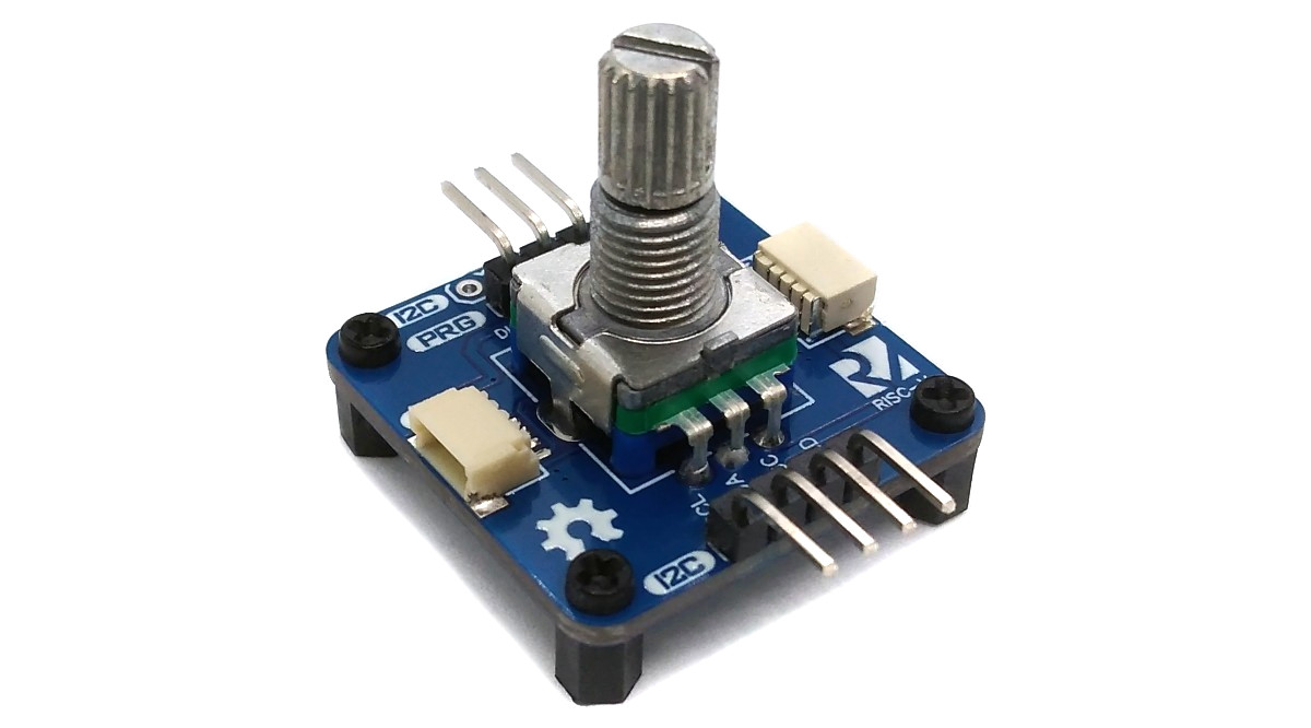
Rotary encoders are a great addition to many projects. However, controlling them typically requires several pins, interrupts, and debouncing. Thanks to this device, a rotary encoder can be easily controlled via the I²C interface, with the built-in CH32V003 handling the rest. By assigning different I²C addresses, it is even possible to daisy-chain multiple rotary encoders. The device is powered through the I²C connection and operates within a voltage range of 2.7V to 5.5V.
The CH32V003 series is a collection of industrial-grade general-purpose microcontrollers that utilize the QingKe RISC-V2A core design supporting the RV32EC instruction set. These microcontrollers are equipped with various features such as a 48MHz system main frequency, 16KB flash, 2KB SRAM, 2.7V - 5.5V supply voltage support, a single-wire serial debug interface, low power consumption, and an ultra-small package. Additionally, the CH32V003 series includes a built-in set of components including a DMA controller, a 10-bit ADC, op-amp comparators, multiple timers, and standard communication interfaces such as USART, I2C, and SPI.
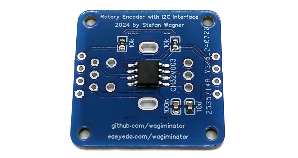
- Take the Gerber files (the zip file inside the hardware folder) and upload them to a PCB (printed circuit board) manufacturer of your choice (e.g., JLCPCB). They will use these files to create the circuit board for your device and send it to you.
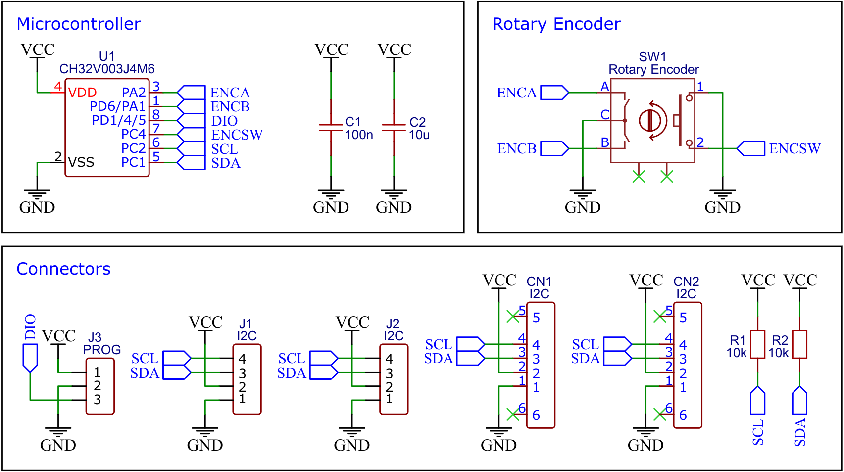
- Once you have the PCB, you can start soldering the components onto it. Use the BOM (bill of materials) and schematic as a guide to make sure everything is connected correctly. You can find the corresponding files in the hardware folder.
- Upload the firmware by following the instructions in the next section (see below).
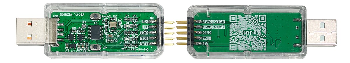
To program the CH32V003 microcontroller, you will need a special programming device which utilizes the proprietary single-wire serial debug interface (SDI). The WCH-LinkE (pay attention to the "E" in the name) is a suitable device for this purpose and can be purchased commercially for around $4. This debugging tool is not only compatible with the CH32V003 but also with other WCH RISC-V and ARM-based microcontrollers.
To use the WCH-LinkE on Linux, you need to grant access permissions beforehand by executing the following commands:
echo 'SUBSYSTEM=="usb", ATTR{idVendor}=="1a86", ATTR{idProduct}=="8010", MODE="666"' | sudo tee /etc/udev/rules.d/99-WCH-LinkE.rules
echo 'SUBSYSTEM=="usb", ATTR{idVendor}=="1a86", ATTR{idProduct}=="8012", MODE="666"' | sudo tee -a /etc/udev/rules.d/99-WCH-LinkE.rules
sudo udevadm control --reload-rules
On Windows, if you need to you can install the WinUSB driver over the WCH interface 1 using the Zadig tool.
To upload the firmware, you should make the following connections to the WCH-LinkE:
WCH-LinkE      I2C-Knob
+-------+      +------+
|  SWDIO| <--> |DIO   |
|    GND| ---> |GND   |
|    3V3| ---> |VCC   |
+-------+      +------+
If the blue LED on the WCH-LinkE remains illuminated once it is connected to the USB port, it means that the device is currently in ARM mode and must be switched to RISC-V mode initially. There are a few ways to accomplish this:
- You can utilize the Python command-line tool rvprog (with -v option).
- Alternatively, you can select "WCH-LinkRV" in the software provided by WCH, such as MounRiver Studio or WCH-LinkUtility.
- Another option is to hold down the ModeS button on the device while plugging it into the USB port.
More information can be found in the WCH-Link User Manual.
Install the toolchain (GCC compiler, Python3, and rvprog):
sudo apt install build-essential libnewlib-dev gcc-riscv64-unknown-elf
sudo apt install python3 python3-pip
pip install rvprog
Connect the I2C-Knob via the 3-pin PROG header to the WCH-LinkE programming device. Open a terminal and navigate to the folder with the makefile. Run the following command to compile and upload:
make flash
Follow the instructions on CNLohr's ch32v003fun page to set up the toolchain on your respective operating system (for Windows, use WSL). Also, install Python3 and rvprog. Compile and upload with "make flash". Note that I only have Debian-based Linux and have not tested it on other operating systems.
- Install PlatformIO and platform-ch32v. Follow these instructions to do so. Linux/Mac users may also need to install pyenv.
- Click on "Open Project" and select the firmware folder with the platformio.ini file.
- Connect the WCH-LinkE to the board, then click "Upload".
WCH offers the free but closed-source software WCH-LinkUtility to upload the precompiled hex-file with Windows. Select the "WCH-LinkRV" mode in the software, open the .hex file in the bin folder and upload it to the microcontroller.
Alternatively, there is an open-source tool called minichlink developed by Charles Lohr (CNLohr). It can be used with Windows, Linux and Mac.
If you have installed Python3 on your system, you can also use the platform-independent open-source command-line tool rvprog for uploading:
rvprog -f bin/i2c_knob.bin
The device has four 16-bit and two 8-bit registers that can be read and written. The 16-bit registers are signed and the least significant byte is always transmitted first. With each access (reading or writing), the registers are always transferred starting with the first in the following order:
- Encoder wheel value (16-bit)
- Encoder switch state (8-bit, 0=switch released, 1=switch pressed)
- Encoder wheel value loop flag (8-bit, 0=do not loop, 1=loop around)
- Encoder wheel minimum value (16-bit)
- Encoder wheel maximum value (16-bit)
- Encoder wheel value change step (16-bit)
An example code for controlling the device is attached. It uses the standard Arduino Wire library, so it should run on almost all supported microcontrollers.
#include <Wire.h>

#define encoder_addr 0x36

int16_t value, lastvalue;
boolean pressed, lastpressed;

void setup() {
  Serial.begin(9600);
  Wire.begin();
  encoder_set(-50, 50, 1, 0, 0);
}

void loop() {
  value = encoder_getValue();
  if(value != lastvalue) {
    Serial.println(value);
    lastvalue = value;
  }
  pressed = encoder_isPressed();
  if(pressed != lastpressed) {
    if(pressed) Serial.println("Switch was pressed");
    lastpressed = pressed;
  }
  delay(20);
}

// Set encoder wheel parameters
void encoder_set(int16_t rmin, int16_t rmax, int16_t rstep, int16_t rval, uint8_t rloop) {
  Wire.beginTransmission(encoder_addr);
  Wire.write((uint8_t)(rval & 0xff)); Wire.write((uint8_t)(rval >> 8));
  Wire.write(0); Wire.write(rloop);
  Wire.write((uint8_t)(rmin & 0xff)); Wire.write((uint8_t)(rmin >> 8));
  Wire.write((uint8_t)(rmax & 0xff)); Wire.write((uint8_t)(rmax >> 8));
  Wire.write((uint8_t)(rstep & 0xff)); Wire.write((uint8_t)(rstep >> 8));
  Wire.endTransmission();
}

// Set encoder wheel value
void encoder_setValue(int16_t rval) {
  Wire.beginTransmission(encoder_addr);
  Wire.write((uint8_t)(rval & 0xff)); Wire.write((uint8_t)(rval >> 8));
  Wire.endTransmission();
}

// Read encoder wheel value
int16_t encoder_getValue() {
  Wire.requestFrom(encoder_addr, 2);
  return((uint16_t)Wire.read() | ((uint16_t)Wire.read() << 8));
}

// Read encoder switch state
boolean encoder_isPressed() {
  Wire.requestFrom(encoder_addr, 3);
  Wire.read(); Wire.read();
  return(Wire.read());
}

This work is licensed under Creative Commons Attribution-ShareAlike 3.0 Unported License. (http://creativecommons.org/licenses/by-sa/3.0/)