Switching properly your home studio devices and speakers the proper way. Control record light sign too with OSC !
In my home studio, I wanted to get the audio device to be switched on and off automatically when my computer starts and stops. I also wanted to get a record light to be switched on when I'm recording stuff.
This would both help me getting ride of manually switching on/off all the piece of audio hardware I have around and most of all, will handle the proper way/order of switching them on/off. E.g. when switching on, turn the audio interface, guitar pedals, etc and then finally turn on the speakers.
So I grabbed a set of 4 Chacon 54662 RF sockets, a XIAO ESP32C3 board and RF 433MHz ASK TX/RX boards (FS1000A transmitter and RF-5V receiver).
The record light sign is turned on/off using a solid state relay I had already. Since I could be recording/stopping, re-recording in a short period of time, I did not want to have a mechanical relay to turn the light on/off. That's why I did not use one the RF socket for that function.
Once everything's plugged and after a few hours of trying to guess the RF protocol for the Chacon 54662 sockets, I came up with the code that's in this repo!
To get even more out of it, I wrote a few Linux scripts that automatically triggers the On/Off commands when booting and shutting down !
Enjoy !
On the microcontroller side (i.e. Arduino, XIAO...), you have to create a file called arduino_secrets.h on the same folder as the .ino sketch file. It must contain the following defines:
#pragma once

#define SECRET_WIFI_SSID        "YOUR_WIFI_SSID"
#define SECRET_WIFI_PASSWORD    "YOUR_WIFI_PASSWORD"

#define SECRET_DAW_COMPUTER_HOSTNAME     "YOUR_COMPUTER_NAME_ON_THE_NETWORK"

// Sequences of 0s and 1s that makes the code to trigger your RF socket
#define SECRET_RF_SOCKET_A_ON_CODE     "000010101001010101010101"   // This is a sample, you should replace it by yours
#define SECRET_RF_SOCKET_A_OFF_CODE    "[ANOTHER SEQUENCE]"

#define SECRET_RF_SOCKET_B_ON_CODE     "[ANOTHER SEQUENCE]"
#define SECRET_RF_SOCKET_B_OFF_CODE    "[ANOTHER SEQUENCE]"

#define SECRET_RF_SOCKET_C_ON_CODE     "[ANOTHER SEQUENCE]"
#define SECRET_RF_SOCKET_C_OFF_CODE    "[ANOTHER SEQUENCE]"

#define SECRET_RF_SOCKET_D_ON_CODE     "[ANOTHER SEQUENCE]"
#define SECRET_RF_SOCKET_D_OFF_CODE    "[ANOTHER SEQUENCE]"
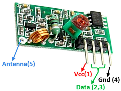
To determine the remote power socket sequences, you must have a RF 433MHz receiver board like this (don't forget the antenna !):

On the Linux side, to get the automatic switch on/off, simply run the following commands:
chmod +x StudioController.sh	# Making the script executable
sudo sh StudioController.sh install		# Install the two scripts that will switch on/off when booting/shutting down
You can also manually switch/on/off by calling the following commands:
sh StudioController.sh on	# Switch on the audio system
sh StudioController.sh off	# Switch off the audio system