No major hardware changes required: just 3 wires from the clock to ESP8266 and (optional) 3 wires to AM2302 humidity sensor.
The following readme text is to be updated to reflect the changes.
Based on https://github.com/zerog2k/stc_diyclock
Firmware replacement for STC15 mcu-based DIY Clock Kit (available from banggood [see below for link], aliexpress, et al.) Uses sdcc to build and stcgal to flash firmware on to STC15W404AS and STC15W408AS series microcontroller.
Basic functionality is working:
- time display 24 hour mode only
- display auto-dim
- relative humidity (%) and temperature (C) display acquired with AM2302 (last 5 seconds every minute or by pressing the Upper button)
- time syncronization from NTP server (updated and saved to RTC DS1302 every 5 seconds)
- the first dot on display starts fast blinking after 30 seconds since last successfull time update on the clock (NTP error or no WiFi connection)
- webserver with http page showing the time, humidity and temperature:


I've removed the following functions unnecessary for me and because I've hit the limit of the RAM (optimizations are needed)
- no date display/set
- no day of week
- no seconds display/reset
- no alarm
-
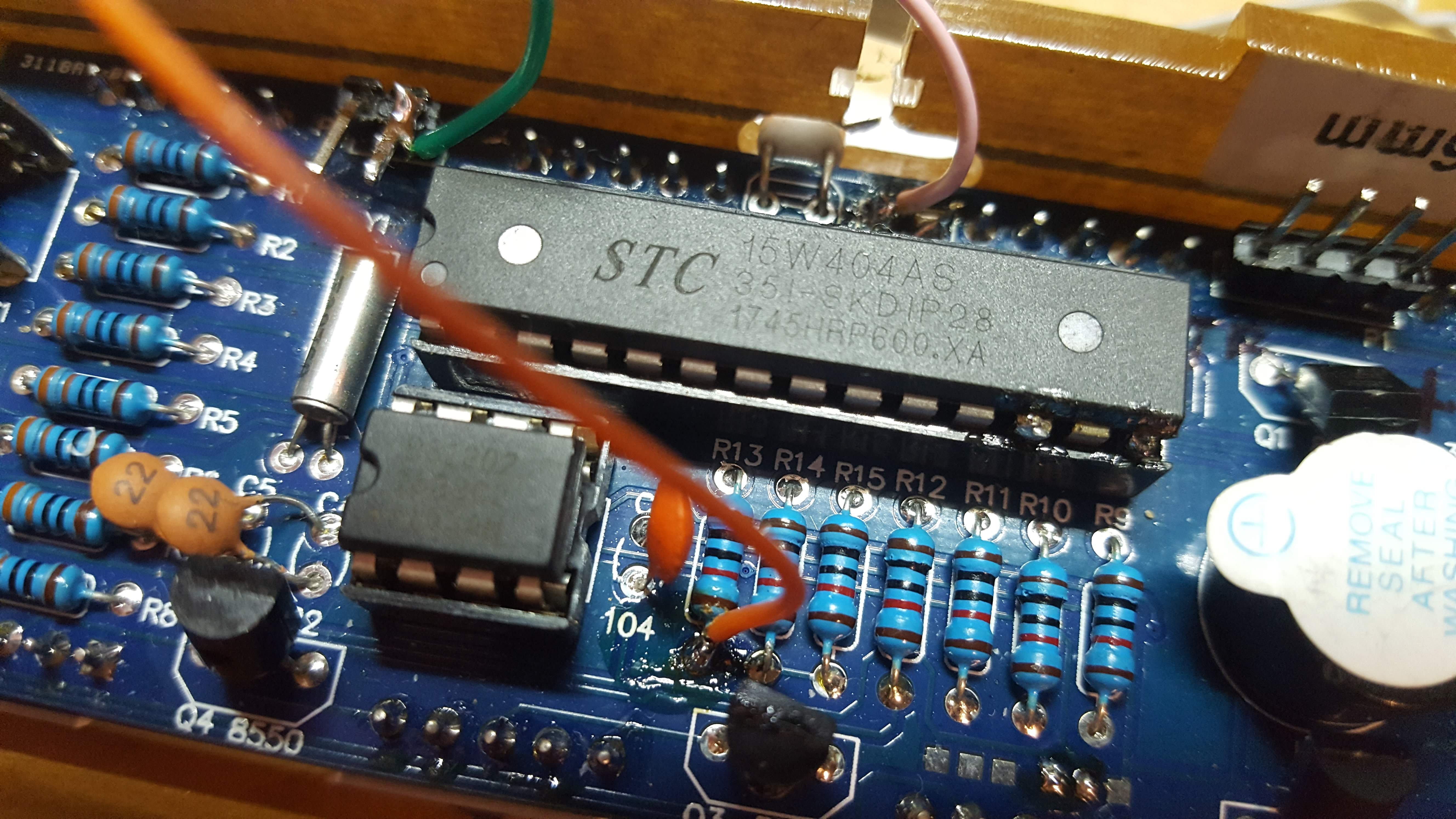
check what is yours STC MC model. Should be STC15W404AS or STC15W408AS. The firmware requires MC with >=4 kB of flash and hardware UART. Get one (or a dozen) if needed on aliexpress
.
-
get ESP8266 WEMOS D1 mini wemos.cc (or clone)
-
get AM2302 humidity sensor (optional)
-
solder on the board the pin headers for UART. On my board it marked as P3. We need only RX line (P3.6 of a MC).
-
solder 3 wires from clock board to ESP8266 module:
| Line | Clock | ESP8266 |
|---|---|---|
| 5V | R13 | 5V |
| RX<->TX | P3.6 | D4 |
| GND | R17 | GND |
- solder 3 wires from AM2302 to ESP8266 module:
| Line | ESP8266 | AM2302 |
|---|---|---|
| 5V | 5V | 1 (Vcc) |
| Data | D3 | 2 (Data) |
| GND | GND | 4 (Gnd) |
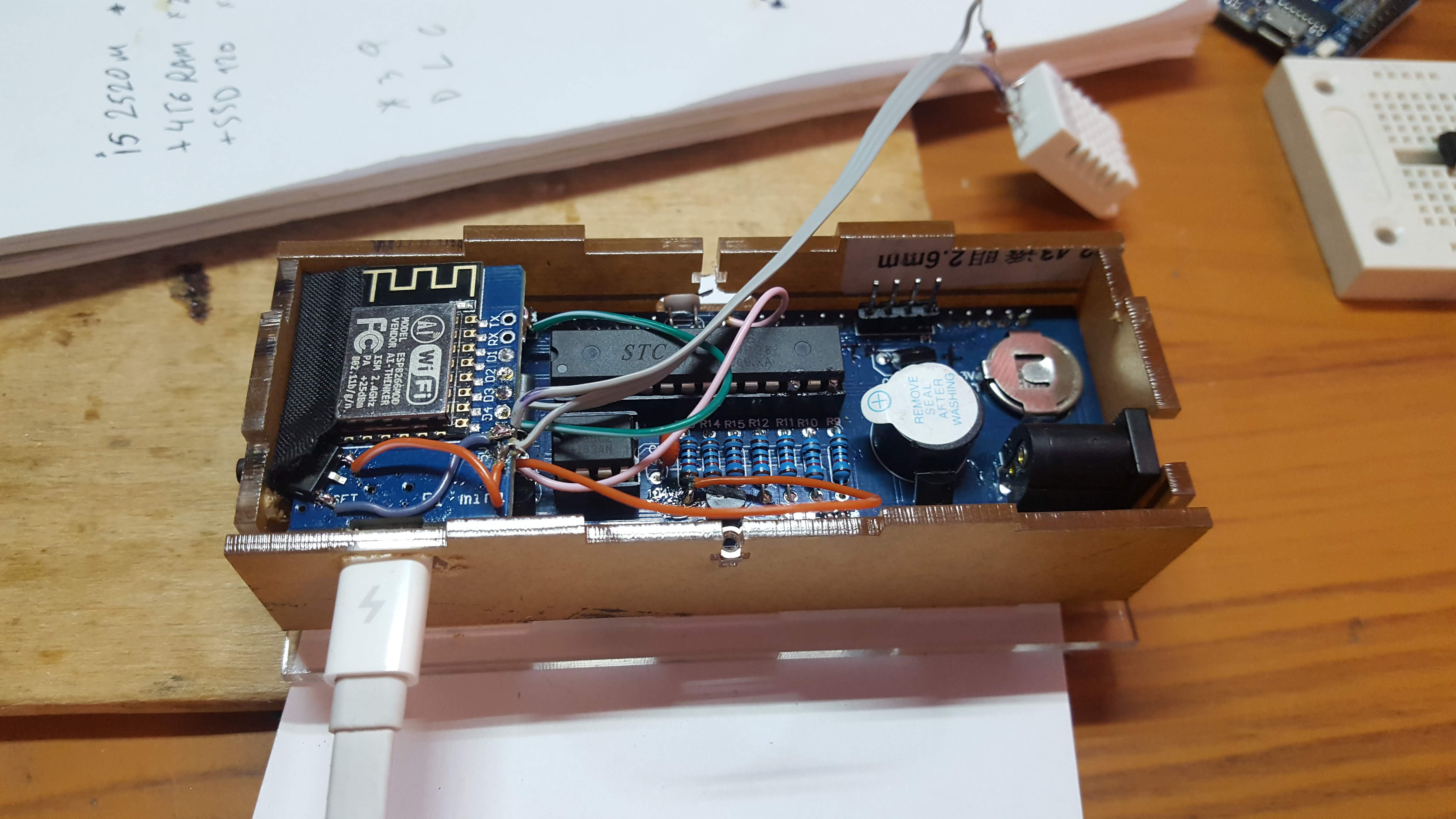
Please ignore an extra 1117-3.3 on my photos: I messed up with 3.3V line on my module and had to solder 1117-3.3 to fix it.
Check out more photos in a folder photos.
-
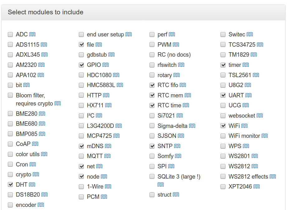
get and upload to ESP8266 https://nodemcu-build.com/index.php Add these modules to the build: dht, mdns, rtcfifo, rtcmem, rtctime, sntp.
-
change variable UTCTZ in init.lua according to your Timezone
-
change WiFI setting in init.lua
-
Using ESPlorer upload init.lua from the esp folder to your ESP8266.
- sometimes some random symbols start to display. A powercycle helps.
- non-responsive button operation
note this project is in development and a work-in-progress Pull requests are welcome.
- chime ?
- fallback to NTC temprature if no AM2302 data recieved
-
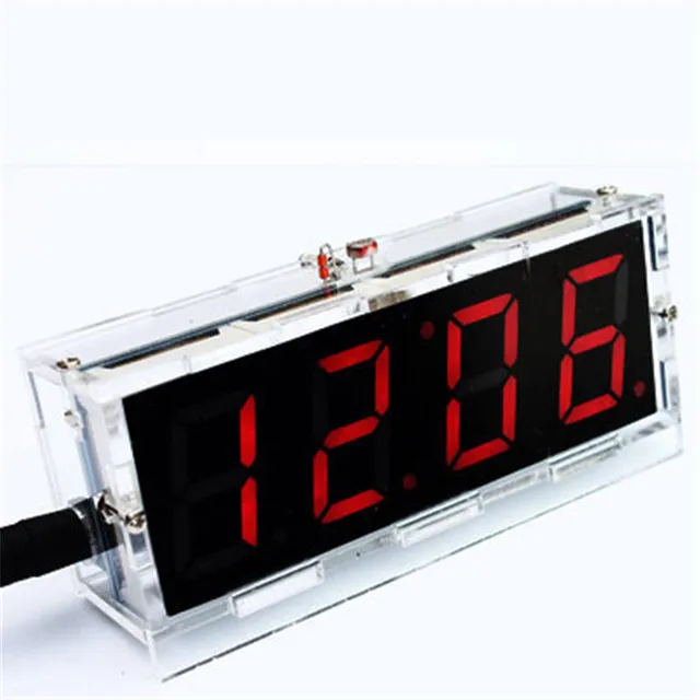
DIY LED Clock kit, based on STC15W404AS or STC15W408AS and DS1302, e.g. I've bought my clock here
-
connected to PC via cheap USB-UART adapter, e.g. CP2102, CH340G. Banggood: CP2102 USB-UART adapter
| P1 header | UART adapter |
|---|---|
| P3.1 | RXD |
| P3.0 | TXD |
| GND | GND |
| 5V | 5V |
- linux or mac (windows untested, but should work)
- sdcc installed and in the path (recommend sdcc >= 3.5.0)
- stcgal (or optionally stc-isp). Note you can either do "git clone --recursive ..." when you check this repo out, or do "git submodule update --init --recursive" in order to fetch stcgal.
*Please check and write a correct serial port name in the Makefile
make clean
make
make flash
If you like, you can try pre-compiled binary: main.hex
Instead of stcgal, you could alternatively use the official stc-isp tool, e.g stc-isp-15xx-v6.85I.exe, to flash. A windows app, but also works fine for me under mac and linux with wine.
~~ note due to optimizations that make use of "eeprom" section for holding lookup tables, if you are using 4k flash model mcu AND if using stc-isp tool, you must flash main.hex (as code file) and eeprom.hex (as eeprom file). (Ignore stc-isp warning about exceeding space when loading code file.) To generate eeprom.hex, run:
make eeprom
~~
This code is provided as-is, with NO guarantees or liabilities. As the original firmware loaded on an STC MCU cannot be downloaded or backed up, it cannot be restored. If you are not comfortable with experimenting, I suggest obtaining another blank STC MCU and using this to test, so that you can move back to original firmware, if desired.
http://www.stcmcu.com (mostly in Chinese)
stc15f204ea english datasheet: http://www.stcmcu.com/datasheet/stc/stc-ad-pdf/stc15f204ea-series-english.pdf
stc15w408as english datasheet: http://www.stcmicro.com/datasheet/STC15F2K60S2-en2.pdf
sdcc user guide: http://sdcc.sourceforge.net/doc/sdccman.pdf
some examples with NRF24L01+ board: http://jjmz.free.fr/?tag=stc15l204
Maxim DS1302 datasheet: http://datasheets.maximintegrated.com/en/ds/DS1302.pdf
VE3LNY's adaptation of this hardware to AVR (he has some interesting AVR projects there): http://www.qsl.net/v/ve3lny/travel_clock.html
original firmware operation flow state diagram
Kit instructions w/ schematic: scan | PDF
