-
Notifications
You must be signed in to change notification settings - Fork 0
Trigger
See list of all supported triggers
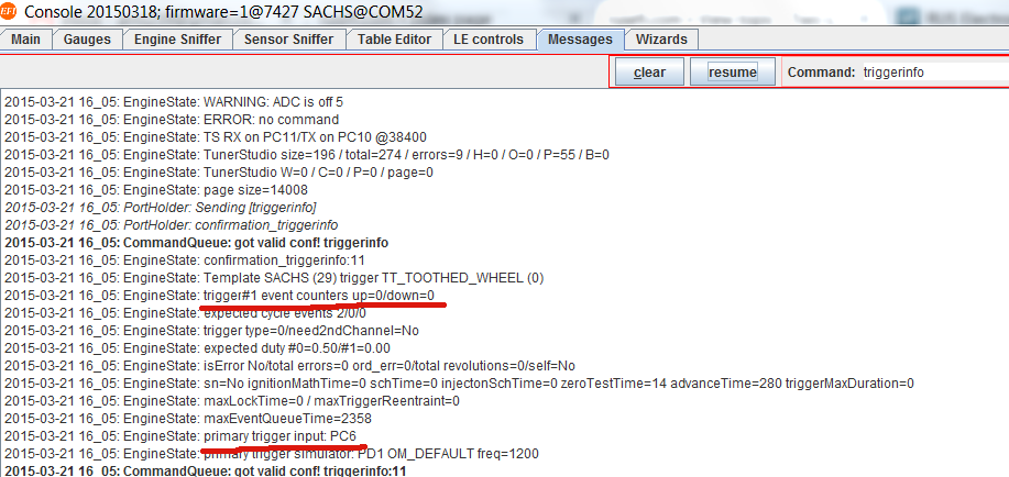
Use triggerinfo command (go to Messages tab, your can either type or use a button from the panel on the right) to confirm input pin(s). Also use triggerinfo command to see how many trigger events were registered by the firmware ("trigger#1 event counters up=x/down=y").
Use reset_trigger to reset counters if needed.
If using an unknown sensor, confirm the sensor signal. In case of Hall type sensor inside distributor, provide power to the sensor and read the output. Typical sensor would be switching from GND to floating.
Next step would be testing the ECU board itself:
test #1: GND input channels 11 and 12, tell me what you read on W211 and W212
test #2: float input channels 11 and 12, tell me what you read on W211 and W212
Type enable trigger_details in rusEFI console to enable verbose synchronization logging. Post from 'Messages" output on the forum.
"print sync details to console" in TS enables the same output but the output still goes only to rusEFI console.
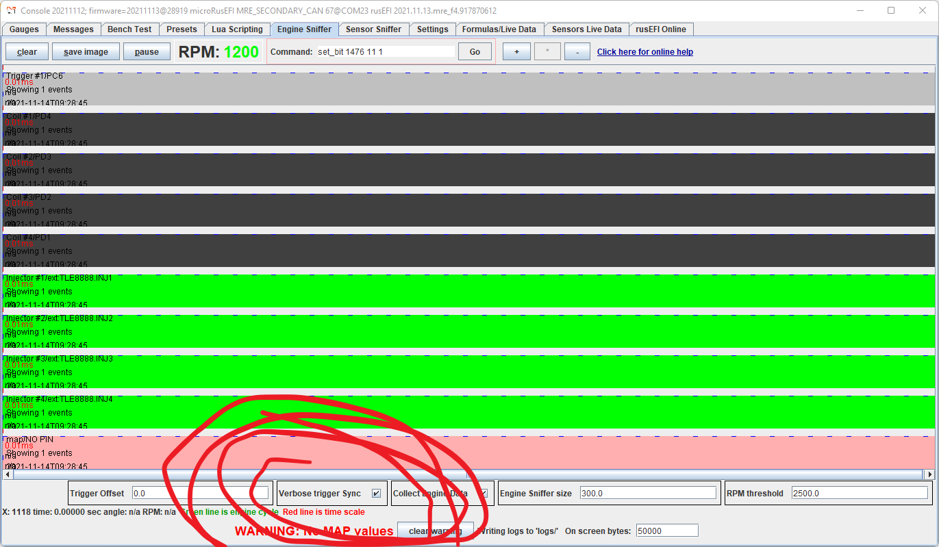
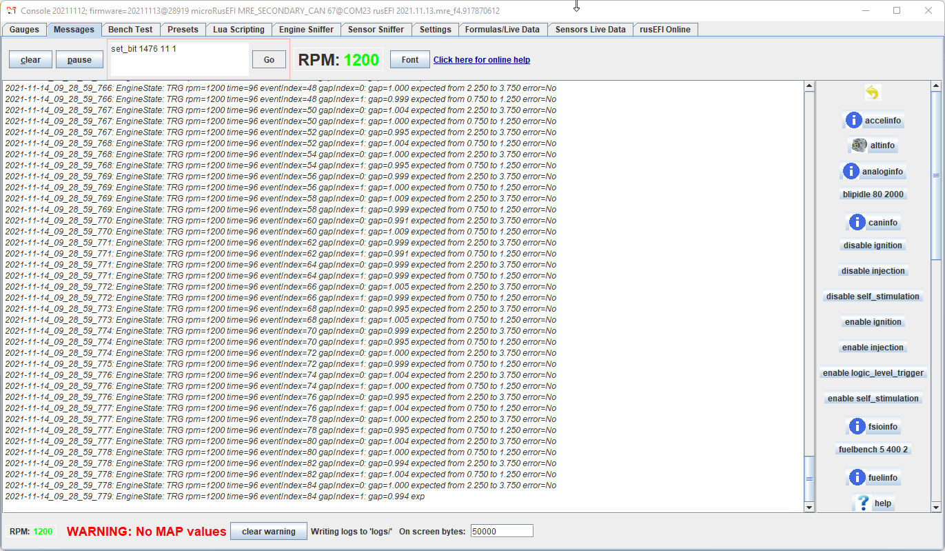
Enable Trigger Counters
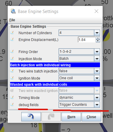
Channel #1 counter would be "debug i1" gauge and channel #2 is "debug i2". These values should go up if you are cranking and that confirms that the events are being registered by rusEFI firmware.
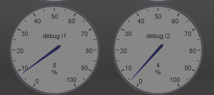
rusEFI has a feature of trigger signal emulation on Trigger Simulator Pins. All channels of trigger input would be simulated on corresponding channels of Trigger Simulator.
At the moment rusEFI has no means for VVT/camInput simulation.
Q: what is globalTriggerAngleOffset configuration parameter?
A: On engine sniffer tab in rusEFI console, there is a signal front with "0" next to it. That's the trigger synchronization event on the primary trigger line. The trigger synchronization always happens at one of the rise of fall of the primary trigger. globalTriggerAngleOffset is the angle distance between synchronization point and cylinder #1 top dead center. TDC#1 is the green line by the way.
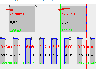
Q: how do I confirm that ECU knows the correct top dead center #1 (TDC) location?
A: Disable injection. Set whole timing map to 0 or to 10, whatever is easier to confirm with a timing gun. Set whole IAT timing correction to zero so that it does not correct your timing. Crank the engine (injection disabled) and confirm that timing advance on the console/TS gauge matches what the timing light is giving you. If there is an offset adjust globalTriggerAngleOffset accordingly. It's a good idea to confirm that the output LED for the corresponding channel is blinking and bench-test spark if possible.
Q: what are ignitionOffset & injectionOffset configuration parameters?
A: there are one of the ways of offsetting the whole timing map or define the injection angle. Both should stay zero under normal circumstances.
Q: where does camshaft signal go and where does crankshaft go?
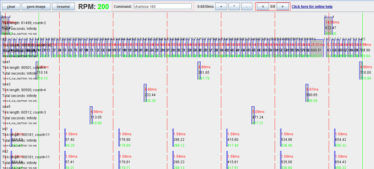
A: it depends, but a rule of thumb is that IF you have BOTH camshaft position sensor and crankshaft position sensor, camshaft is always trigger#1 input and then crankshaft is trigger#2. This case we use trigger#1 (cam) to know which cylinder is which, and trigger#2 (crank) to know precise angle position.
Here is a picture with a one-teeth cam sensor and a 60/2 crank:
Q: what does total errors mean in triggerinfo output?
A: this is total count of how many times we detected unexpected number of teeth per trigger cycle since ECU reboot. isError means that we had issues with 4 of the last 6 cycles. We also turn triggerErrorPin on in case of trigger error - you can put an LED to see trigger error. total errors also could be displayed as TS gauge.
Q: Sync is not reliable, how do I see more details?
A: try enable trigger_details command in console or "print sync details to console" option in TS. This would produce some helpful messages with synchronization progress details.
Q: I have a 60/2 crank wheel and I would like to use a cam sensor for fully sequential mode. Should I use "4-stroke with Cam sensor"?
A: You can only use "4-stroke with Cam sensor" if your composite trigger shape is known to rusEFI. If you are adding a cam to 60/2, rusEFI probably does not know this combination with all the angles precisely. The way to add sequential to a skipped-tooth crank wheel is via cam input mode, same as used for VVT (see also VVT) This case your known crank shape is used for shaft position lookup and your cam is only used for phase lookup - exact cam sensor angular position is less important.
See also VVT
- How to search the Wiki
- Quick Start
- How to ask questions
- Support
- How to create a TunerStudio project
- HOWTOs and FAQs
- rusEFI project overview
- rusEFI Online
- rusEFI virtual simulator
- Fueling
- Multispark
- Cranking
- Electronic Throttle
- Knock Sensing
- Variable Valve Timing
- Lua Scripting
- GDI
- Digital Dash
- rusEFI Hardware Overview
- Wiring & Connectivity Overview
- rusEFI Assembly Completeness Chart
- Kit Instructions
- Hellen Miata 90-95
- Hellen Miata 96-97
- Hellen Miata 99-00
- Hellen Miata 01-05 VVT
- MREAdapter55: from Lada to e30
- Frankenso MazdaMiataNA6 PnP
- Creating a PnP PCB
