-
Notifications
You must be signed in to change notification settings - Fork 195
Hardware variants
#Tested configurations: T-962 with an LPC2134/01 MCU - OK
#Reported configurations in the field: T-962 and T-962A ovens and LPC2144 and LPC2148 MCUs
These should all be functionally equivalent to the model used during development but it would be great to get feedback on successful/failed attempts from people that are willing to try it out.
#Variant A
Production date for this unit is 09.06 (as shown on back panel).
Known differences:
- Uses LPC2144 (instead of LPC2134)
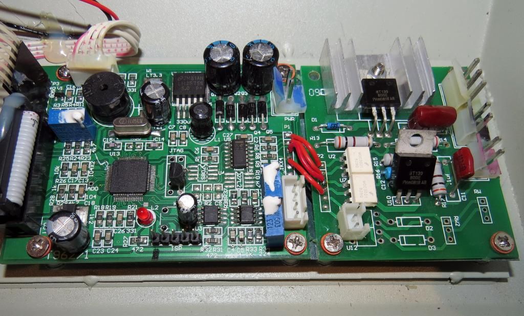
- PCB is actually two separate boards connected with wires (rather than single PCB)
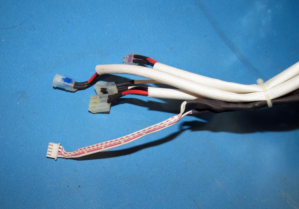
- Thermocouples are spliced to copper wires that run to 4 pin connector on PCB (rather than terminal block on PCB)
- Various minor parts placement changes
View of PCB:
View of wiring harness:
Connection to thermocouple wires is under black shrink tubing.
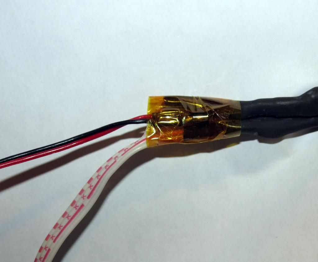
Addition of DS18B20 sensor to wiring harness.
Sensor must be near the "cold junction" where the thermocouple wires connect to copper wires. Here the sensor is placed under tape wrapped around the junction on the thermocouple wiring.
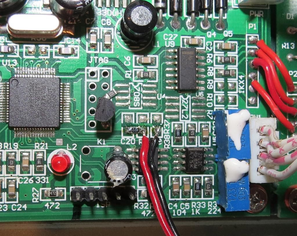
Temperature sensor wiring to PCB.
Add 4K7 resistor and wires to pads as shown.
Red wire: 1-wire signal. Black wire: ground.
Note: This is only for Variant A. Units with terminal block should use directions here.


