-
Notifications
You must be signed in to change notification settings - Fork 195
Flashing the LPC21xx controller
The latest hex file can be found here: https://github.com/UnifiedEngineering/T-962-improvements/releases
Flash utility: http://www.flashmagictool.com
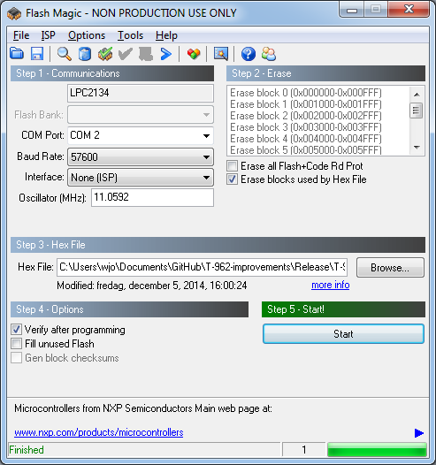
Settings to be able to communicate with the board:

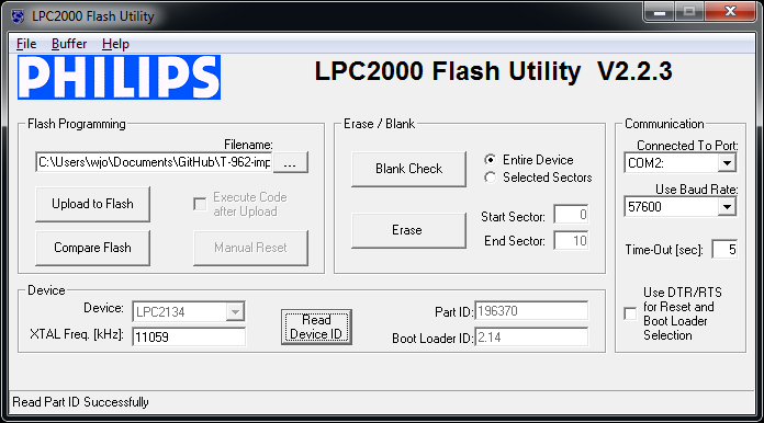
An older flash utility for Windows that is known to be working with the LPC2134/01: http://www.lpctools.com/downloads/LPC2000%20Flash%20ISP%20Utility%20v2.2.3.zip
if you get an error saying that the dependency mscomctl.ocx is missing when trying to run it, install the Microsoft Visual Basic 6.0 Common Controls
https://www.microsoft.com/en-us/download/details.aspx?id=10019
To flash, you need only TTL serial - a USB->serial with the correct voltage level (3.3V) should do the trick; an actual ISP tool for NXP LPC 2000 will do fine, but many other cheaper options should work fine.
Settings to be able to communicate with the board:

Note that the XTAL frequency has to be entered for a successful connection to be made. I certainly hope that all ovens have been built with the same frequency XTAL (11.0592MHz which will be entered as 11059 (kHz) in the LPC Flash utility and 11.0592 (MHz) in Flash Magic).
Also the baudrates choices are fairly limited and depend on the chosen XTAL frequency. 57600 is the fastest one that will work with the 11059kHz setting.
Using Flash Magic I have had some problems getting the connection to work at 57600. I overcame this by setting the baud rate to 14400 which enabled the software to read the device signature and reflash the controller successfully. Interestingly at 9600 it doesn't work, but some people reported it working at that speed.
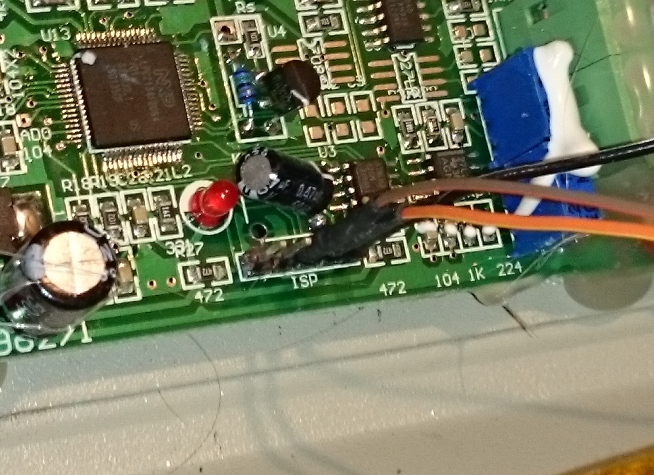
ISP pinout from left to right if looking at the board so the ISP text can be read:

-
n_ISP(connected to GPIO0.14, ground during reset to enter ISP mode) -
n_RESET(active low reset input) -
TXD0(UART0 output to host, LVTTL 3.3V) -
RXD0(UART0 input to MCU, LVTTL 3.3V) -
Ground(this ground is floating with respect to earth ground in the mains connector and chassis)
For flashing -- you can enter bootloader mode manually, and not require nISP or nRESET to be wired up to any ISP or serial tool. To flash over the serial, all you really need is RX, TX, and GND (possibly a voltage reference, see below.)
Important note to noobs like me: When you connect the USB flash tool and oven, you need to do it this way; 1:1 does not work.
-
TXD-->RXD -
RXD-->TXD -
GND-->GND
- Ground
n_ISP - Ground and release
n_RESET - Release
n_ISP - Activate LPC2000 Flash Utility on the correct COM port
- Select Read Device ID and hit OK/Enter to dismiss the "please reset your board now" dialog.
- Dump flash or Upload new hex file
- Change LPC2000 COM-port to a different port (doesn't matter which one), as otherwise the program will continue to hog the COM port and you can't hook up a terminal program to it.
- Pull
n_RESETlow briefly again to start the software again. - If running this firmware you will have debug output on the same serial port as the programming happened on but at 2Mbps,n81. (Edit. Debug output in the latest firmware appears to be 115200 N 8 1)
It's normal behavior to see both green LEDs on the front panel turn on or flicker when in ISP mode. This is a result of floating pins driving the buffers that drives the optocouplers. This means that both heater and fan may very well run at 100% duty cycle during the few seconds it typically takes to flash the controller. You can fit weak pull-up resistors on both outputs (P0.8 and P0.9) to get rid of the problem, however once the new firmware is loaded you can use the alternate bootload sequence which avoids turning on the fan & heater (discussed next).
The minimum trigger to enter the hardware boot loader is nISP to be held low when reset goes to high (chip running.) An example is to jumper nISP to GND and then power on the oven - it will then be in bootloader mode.
Unified Engineering Firmware versions after 0.2.1 include the following alternate bootload enter sequence, which keeps the fan and heater off during the bootloading process, along with an easier method of entering the bootloader if you don't have USB-Serial that can control n_ISP / n_RESET. (The original firmware supplied in the oven does not support this feature.)
- Turn oven off (and wait a few seconds)
- Hold F1 button down
- Turn oven on
- The display should be blank, you can release the F1 button now as it's in bootload mode.
- Run bootloader software of your choice (see previous instructions)
- Turn oven off/on again to run new firmware
When the oven is freshly powered up and in bootloader mode, the oven screen should be either blank or garbage - not showing any graphic or sensible menu.
If you have a terminal mode (such as Flash Magic, or minicom on linux, or any serial terminal on your wiring) the protocol for the bootloader is .... enter bootloader mode, then enter a "?" (no quotes) keystroke; the LPV cpu should respond with "Synchronized"; you then enter "Synchronized" back to handshake. Other commands are possible (see the LPC2134 datasheets for some discussion.)
If you put in ? and nothing happens - you are either not in bootloader mode, or the wiring is not correct, or the baud rate is not being managed by the LPC. If you are getting some garbage back on the terminal, your baud rate could be icorrect, or wiring.
(Verify that RX and TX are not swapped; you could get sensible garbage back, and still have RX swapped!). Also, try changing the speed from 57600 to 14400 or 9600. This might do the trick.
If your serial needs a voltage ref for the TTL serial, you may need to add a 3.3V line from the oven pcb (none is exposed in the header unfortunately. At least one person tried using nRESET and nISP as voltage reference since they are normally held to 3.3V during operation, but without luck; in that case, manually soldering a wire to the resistor to the immediate right of the ISP header on the pcb provided a useful 3.3V reference point.)
Using this tool: http://sourceforge.net/projects/lpc21isp/, (after entering the bootloader) it's a matter of
./lpc21isp -hex build/T-962-controller.hex /dev/ttyUSB0 57600 11059
The lpc21isp tool has other options such as -termonly to enter a terminal.
The tool is easily compiled under win32 using Visual Studio or linux/BSD using gcc. For cygwin builds the lpc21isp.h misidentifies target and doesn't #define stricmp to strcasecmp so will fail in the build; simply comment out the preceeding #ifdef and following #endif to force the two #defines to function and the build will succeed.
lpc21isp will work fine in cygwin as a result.
lpc21isp will also work under VirtualBox VM on a Windows host.
Lastly, it is available on Mac using brew...
brew install lpc21isp
The FlashMagic utility has been updated since the above screenshots were made. Here's screenshots of a later version of FlashMagic and showing the configuration settings I used to successfully upload the hex file which was dated Feb 4, 2018 ( ~180KB ).