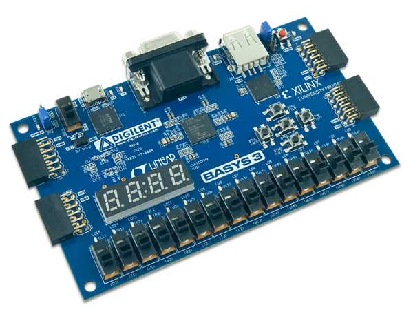
This project contains the Verilog HDL code for implementing a PMODE step on the Basys3 FPGA development board.
The PMODE step is a useful circuit for controlling the direction of rotation of a stepper motor. The PMODE step circuit consists of four switches (SW0-SW3) and four output pins (LED0-LED3). When the switches are pressed in a particular sequence, the corresponding LED pins will light up in a particular sequence. This sequence of LED pin activations determines the direction and speed of the stepper motor.
The PMODE step circuit is implemented using Verilog HDL. The design consists of a state machine that controls the behavior of the circuit based on the input from the four switches. The state machine has four states, each corresponding to a particular sequence of LED pin activations. The state machine transitions between these states based on the input from the switches.
The Verilog HDL code is written to be compatible with the Basys3 FPGA development board. The input signals are read from the switches and the output signals are written to the LED pins on the board.
To use this Verilog HDL code on the Basys3 FPGA development board, follow these steps:
- Clone or download this repository.
- Open the project in a Verilog HDL synthesis tool such as Xilinx Vivado or Intel Quartus Prime.
- Synthesize the design and generate the bitstream.
- Program the bitstream onto the Basys3 FPGA development board.
Once the bitstream has been programmed onto the board, you can test the circuit by pressing the switches in the appropriate sequence and observing the LED pins.
This project was developed by Feanor1021. The author would like to acknowledge the contributions of the Xilinx Vivado and Intel Quartus Prime tools to this project.
This project is licensed under the MIT License. See the LICENSE file for details.